This project is a full-stack mechatronic bionic arm that translates human hand gestures into real-time physical articulation. To move from proof-of-concept to production-grade reliability, the development spanned rapid breadboard prototyping, custom PCB engineering, power regulation under dynamic load, and host-side computer vision integration.
FIG 1.0 — System Demo: Computer vision pipeline extracting 3D hand landmarks and streaming low-latency kinematic motion to the bionic arm.
Phase 1: Rapid Prototyping & Breadboard Proof-of-Concept
The initial phase focused on validating the kinematic link between computer vision outputs and physical actuation. Using MediaPipe, real-time spatial coordinates of hand joints were mapped to PWM servo angles. A breadboard setup was built to test multi-servo power draw, confirm I2C protocol communication with a PCA9685 PWM driver, and isolate control lag during live gesture tracking.
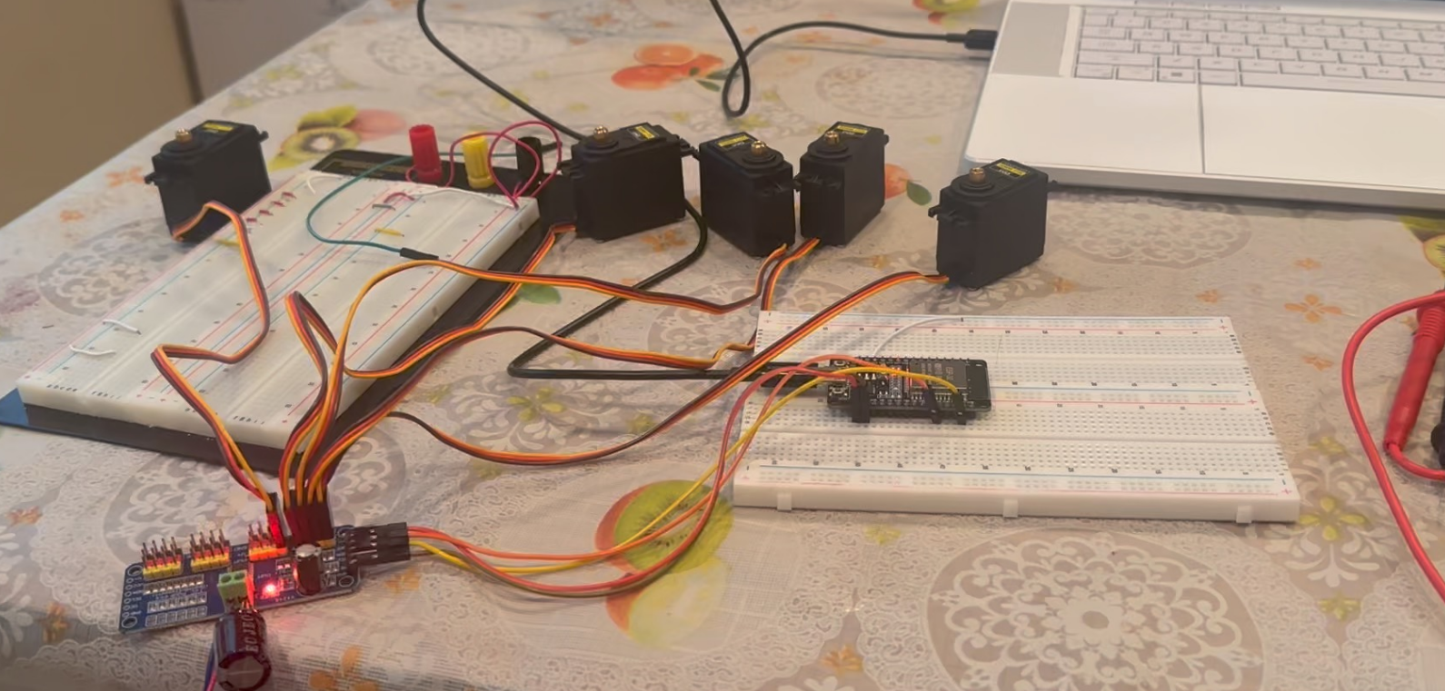
FIG 1.1 — Phase 1 Bring-Up: Early breadboard prototyping to validate signal routing, I2C logic, and multi-servo current demands before PCB layout.
Phase 2: Embedded Architecture & Custom PCB Design
To eliminate wire clutter, signal noise, and power instability inherent to breadboards, I engineered a dedicated 2-layer PCB in KiCad. The board pairs an ESP32-S3 microcontroller with a PCA9685 16-channel PWM driver and integrates an onboard AP63203 buck converter to step down high-current servo power supply rails down to a clean 3.3V logic rail.
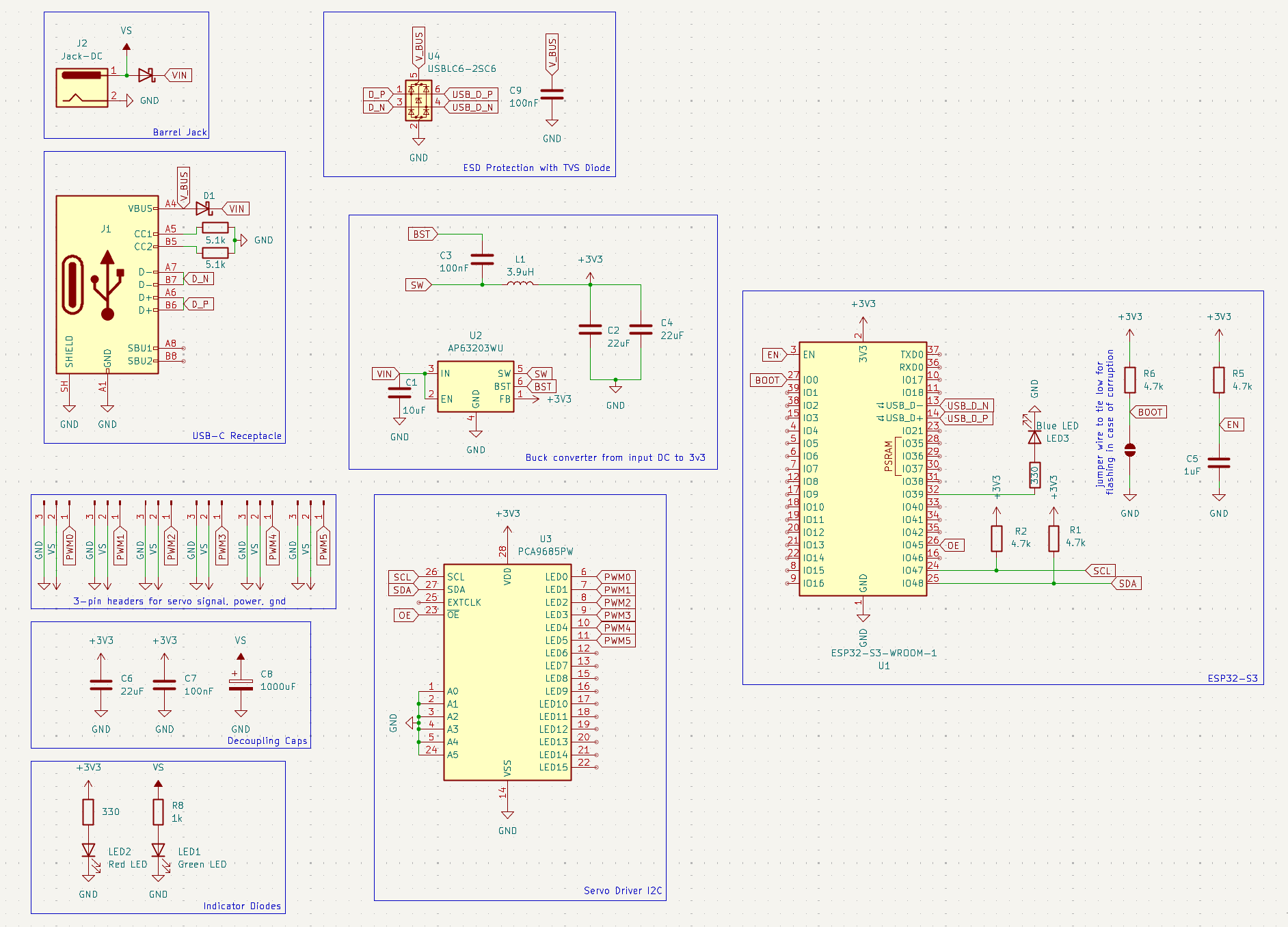
FIG 1.2 — Schematic Capture: Circuit blocks featuring USB-C ESD protection, AP63203 3.3V buck regulator, and PCA9685 PWM logic.
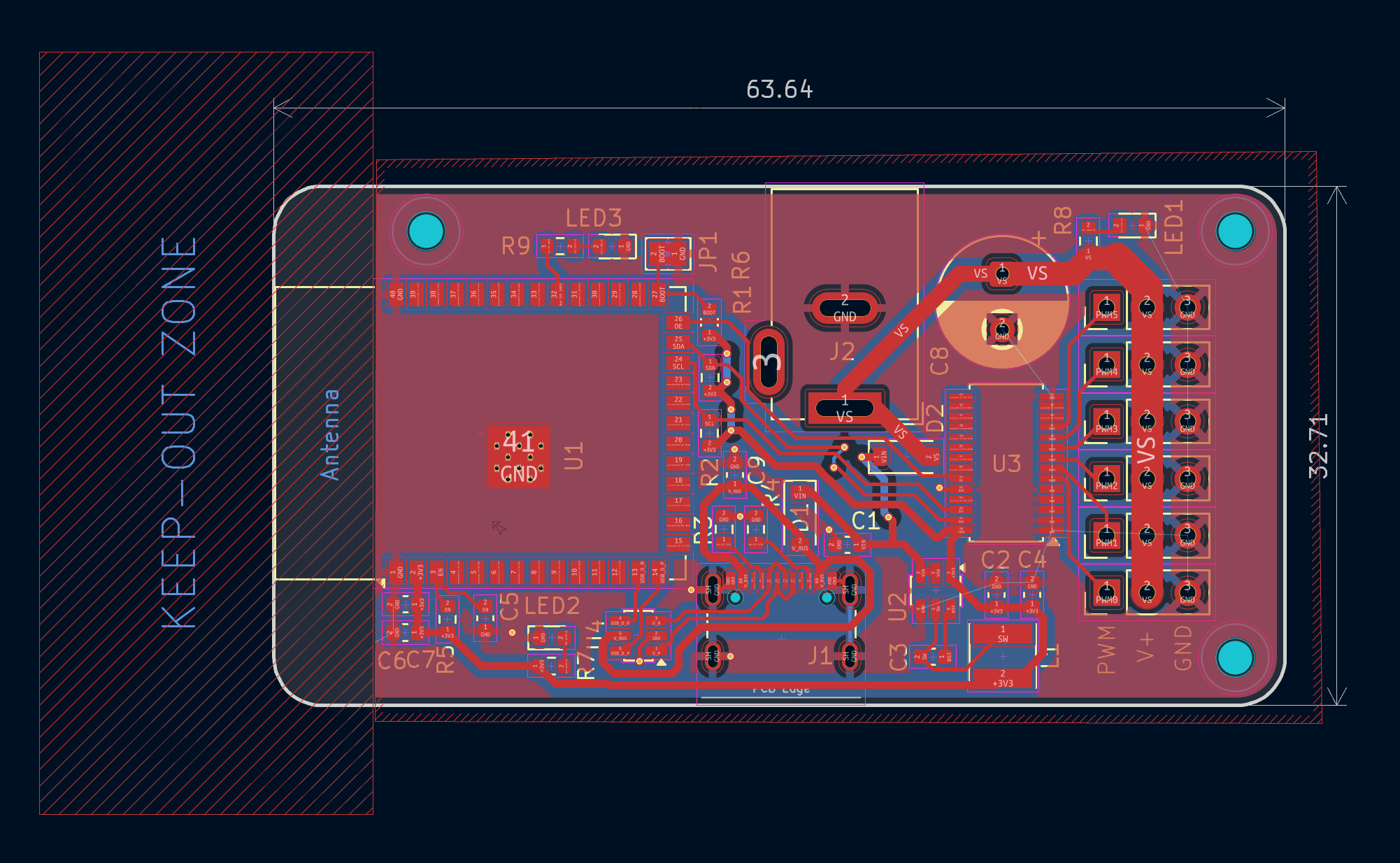
FIG 1.3 — PCB Routing: Optimized ground planes, high-current power traces, and differential routing for native USB lines.
Phase 3: Robust Power Integrity & Hardware Bring-Up
To ensure system survival under heavy inductive motor loads, the hardware features an engineered reverse-current protection stage. High-side Schottky protection and bulk decoupling capacitors suppress massive back-EMF voltage spikes generated during sudden multi-servo action, isolating sensitive ESP32 logic from power-rail collapse.
Hardware testing exposed critical edge cases under physical load, particularly servo stalling caused by missing software motion bounds. Implementing strict minimum and maximum angle limits prevented motors from over-rotating past mechanical stops, reducing stall current and protecting current-sense components. Additional bring-up work involved diagnosing bootloader strapping-pin contention by cutting and rerouting the IO0 and JP1 trace constraint to ensure clean cold boots.
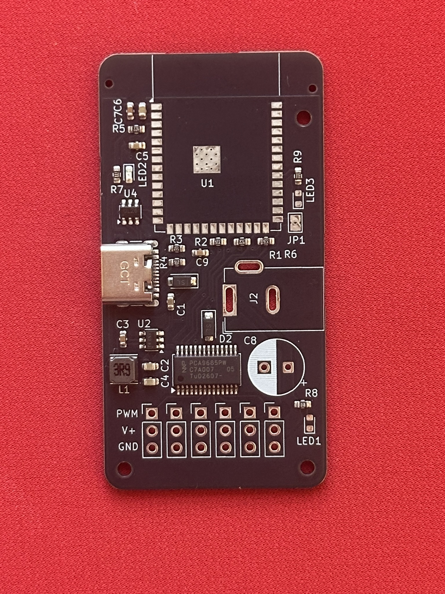
FIG 1.4 — Custom Controller: Assembled custom ESP32-S3 control board post-manufacture and verification.
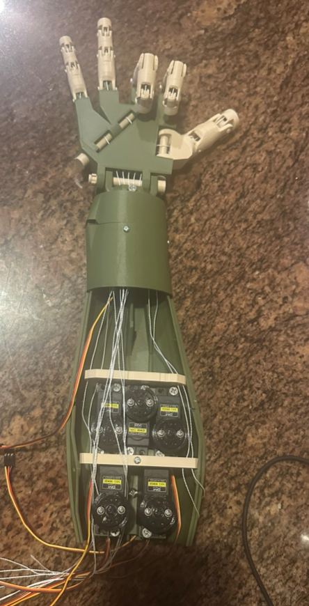
FIG 1.5 — Physical Integration: Fully assembled bionic arm chassis with servo tendon linkages and mechanical mounts.